Signal Tower
Yet another continuous integration status indicator for agile software development teams
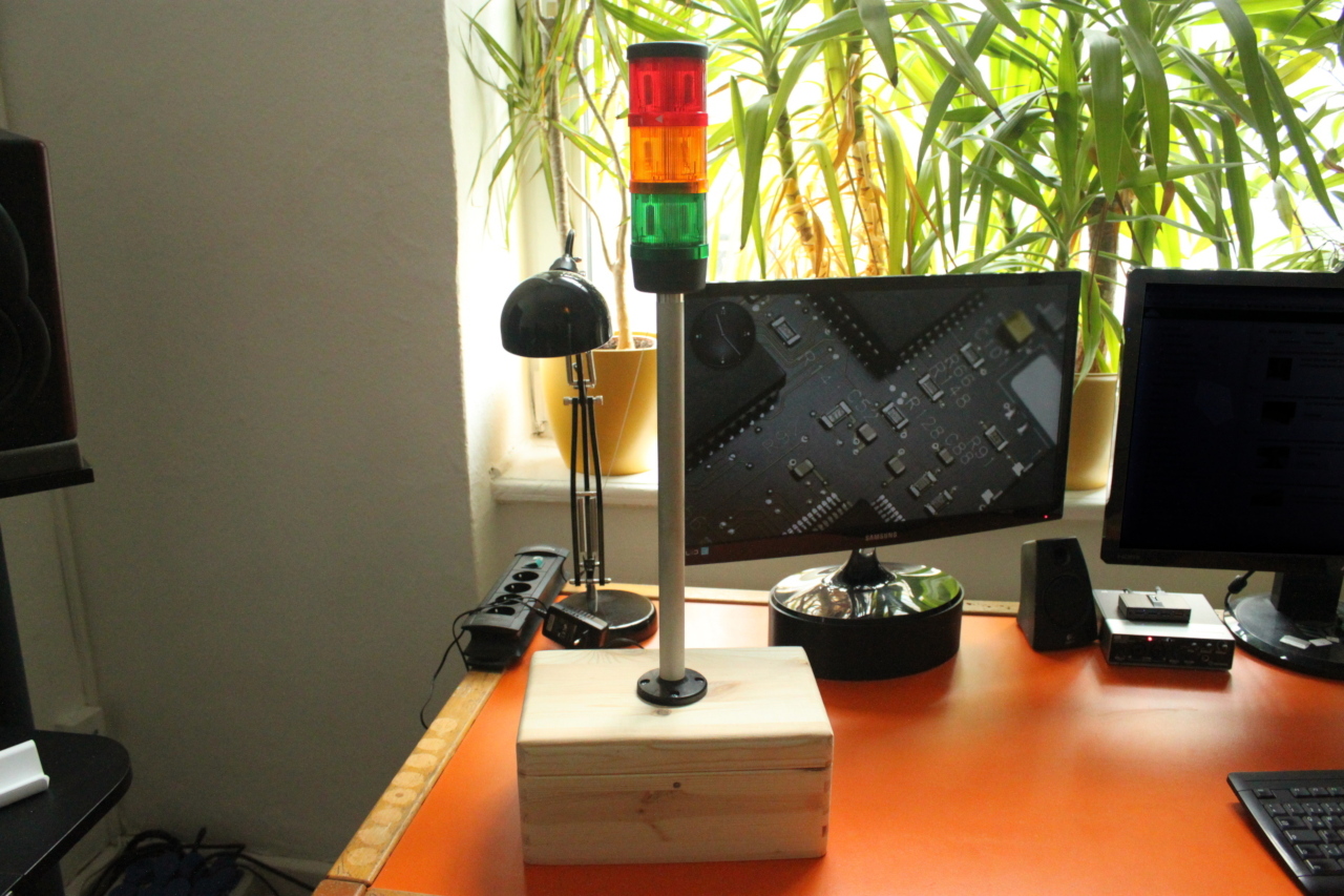
Signal towers (or stack lights) are usually used in industrial manufacturing and display the state of a machine to the operators. They are mounted on a pole, which makes it easy to spot a malfunctioning machine from far away. Different colors can be used to display various conditions (for example green = normal, red = malfunction, yellow = warning, blue = good, but low on raw materials).
Nowadays software development is also partly regarded as an industrial process. For example continuous integration and deployment can be fully automated. When a developer pushes new code into the central repository, this code can be automatically build, tested and deployed onto production servers. Testing is an essential part of this process, since you don't want bad code to creep into production.
A fast feedback of these problems to the developers helps them to quickly react accordingly. So today more and more development teams are installing some kind of easily perceptible good/broken-indicators. This can either be a big monitor which displays some kind of a build status dashboard, or a stylish industrial signal tower like the one in the picture above.
The following documentation describes how you can build such a signal indicator with an Arduino board, a custom shield (or a breadboard construction) and a WLAN module. The firmware implements a small HTTP server, which allows you to control the signal tower through some simple HTTP REST APIs.
 Project Files
All of the project files (schematic, PCB layout, firmware source code) are hosted on GitHub:
https://github.com/grappendorf/signal-tower
Parts needed
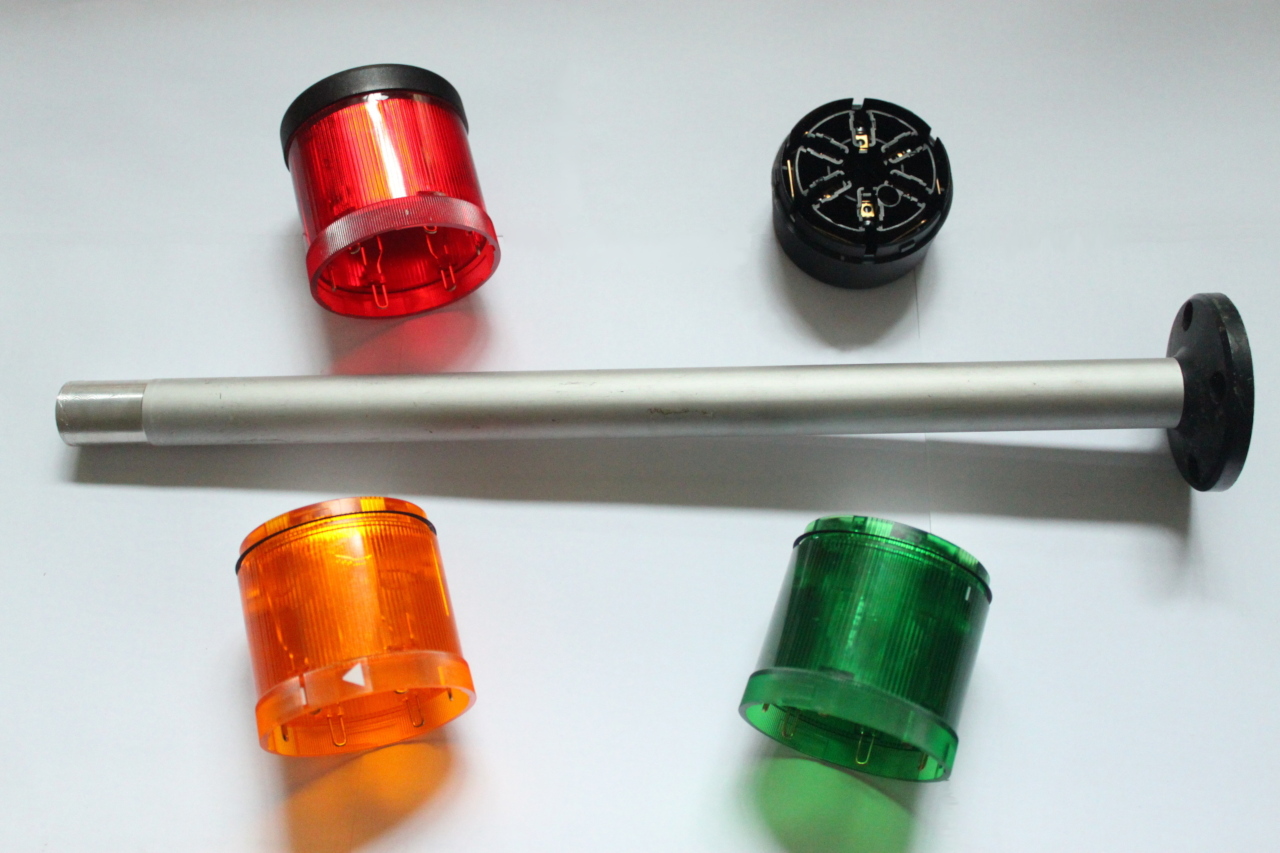
I'm using a Werma Signal Tower because this was the first one i was able to score on ebay for a few bucks. There are other manufactures of this quite expensive professional gear, for example Patlite or Signaworks. My signal tower was delivered without bulbs, but this was of no disadvantage, because these bulbs are halogen lamps which i wanted to replace with LEDs anyway.
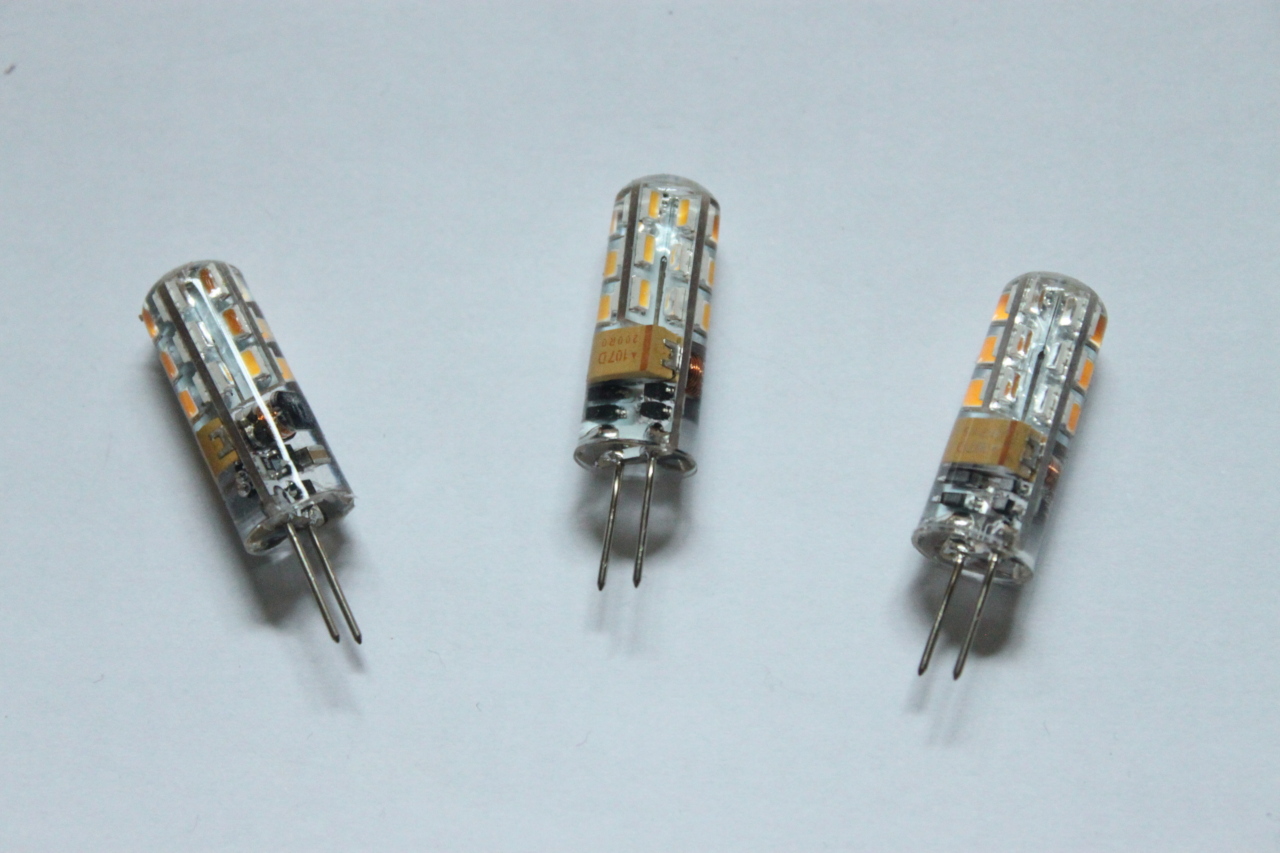
The following image shows some 12V LED lights which are intended to replace 12V halogen lamps. These LEDs are ideal for this application, because they are designed to distribute their light over a horizontal range of 360 degrees.
We also need a solid, somewhat heavy case. This is a wooden box that I found at a local hardware store:

What else do we need:
- An Arduino board
- A Microchip WiFly module or an ESP8266 module
- Three TIP110 (or any other power transistor)
- A photoresistor (only if you want to dim the lights during night times)
- A 12V to 5V DC-to-DC converter (e.g. Traco Power TSR 1-2450)
- 12V power plug
Mount the LEDs
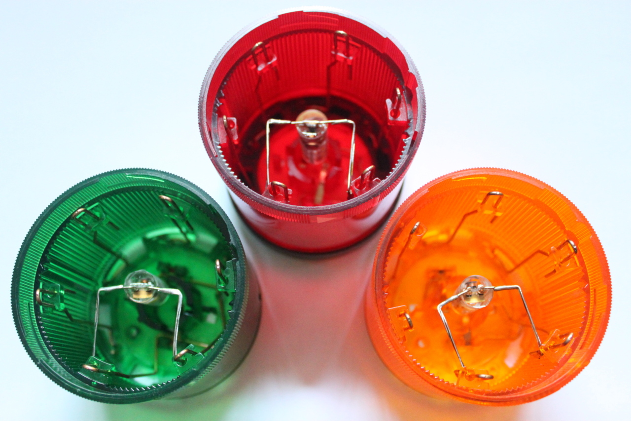
I simply soldered the LED lamps directly to the contacts of the signal tower modules.
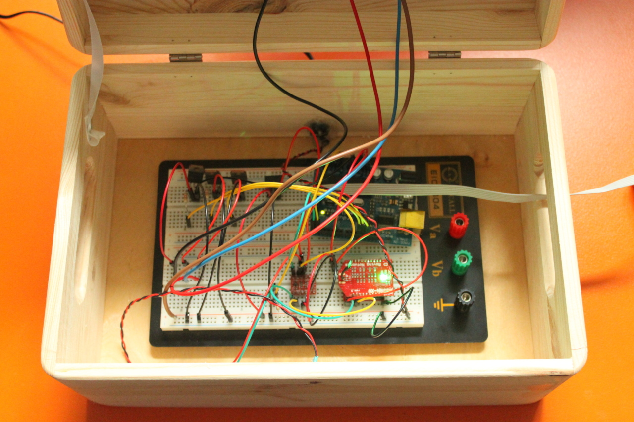
Prototyping
I always build a prototype on a breadboard before I start to design and manufacture the PCB. But you could stay with this breadboard build if you don't want to create your own PCB. Another option would be to use an Arduino prototype shield.
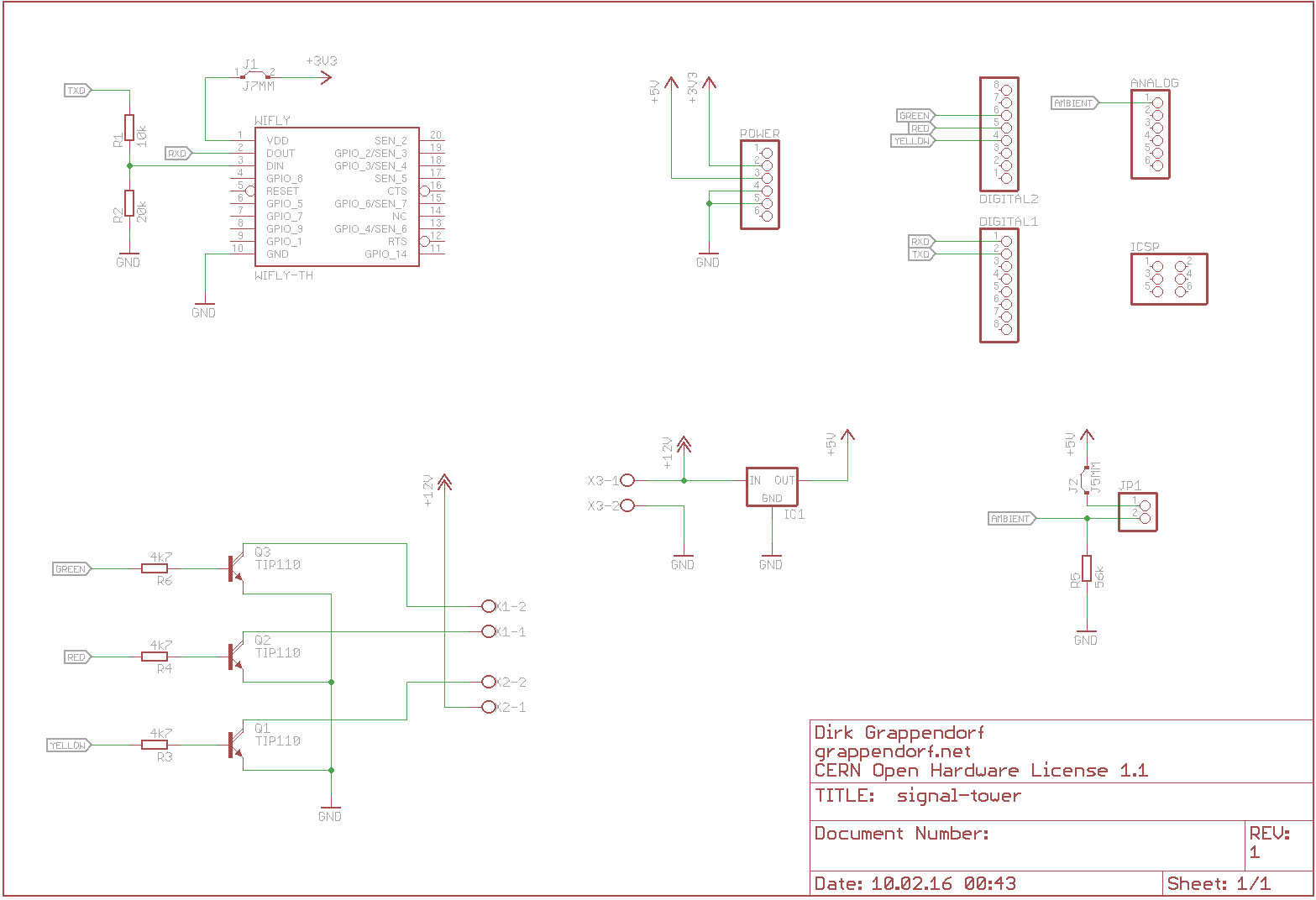
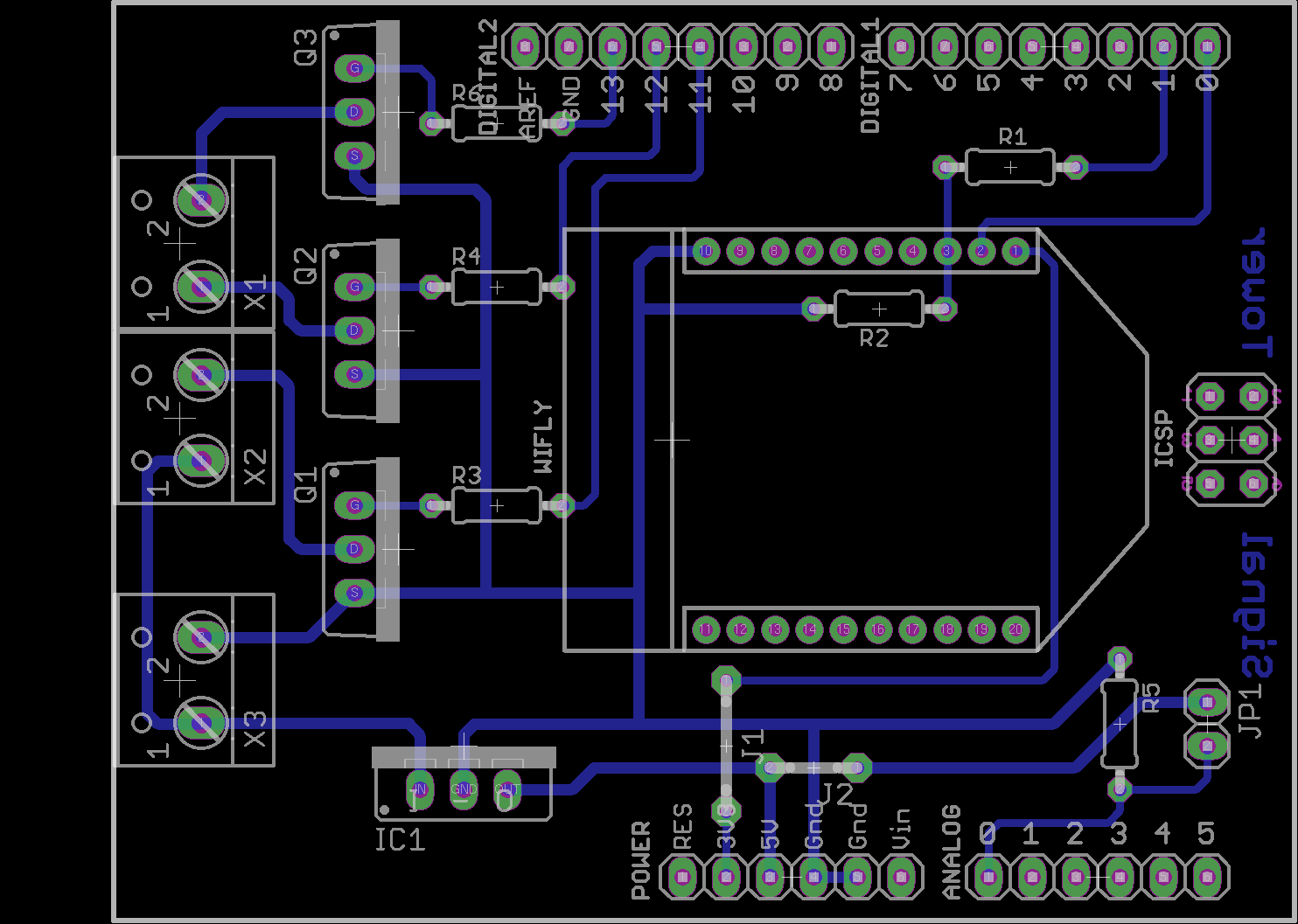
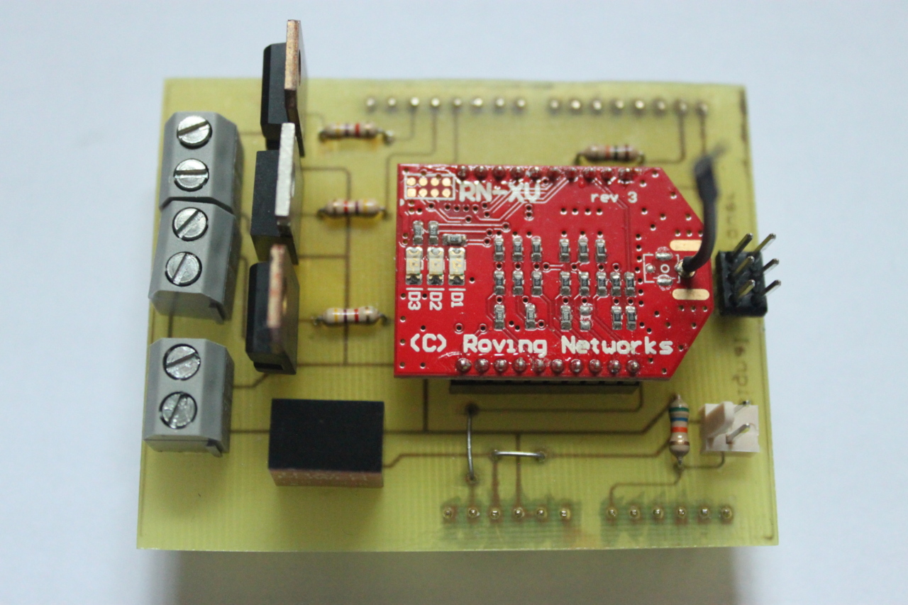
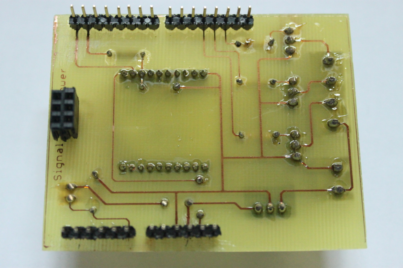
PCB
This is my final schematic and PCB for an Arduino shield. This is designed for a WiFly module. If you prefer an ESP8266 module, you need to modify this design.
The circuit is quite simple. Three power transistors driving the 12V LEDs are connected to three Arduino IO pins. The photoresistor and a 56k Ohm resistor (depending on the type of photoresistor you choose) form a voltage divider, and its signal is connected to an Arduino analog input. The DIN and DOUT signals of the WiFly module are connected to the TX and RX lines of the Arduino hardware serial port (TX goes through a voltage divider because the WiFly module has 3.3V IO). This means that when the WiFly module is plugged in, you cannot use the Arduino USB port anymore and need to program the firmware via the ISP port. Eventually the 5V output of the DC-to-DC converter is fed into the 5V pin of the Arduino board.
Action!
And here you can see the signal tower in action:
Firmware
The firmware software is made as simple as possible. I pre-configured the WiFly module with a terminal program and an USB to serial adapter and stored the SSID, the passphrase and the serial communication settings in the module before mounting it onto the PCB. It is possible to perform all of the configuration from within the firmware, but since I don't need to change the configuration later on, I've omitted this code.
The WiFly module must be configured to transparently pass the TCP data through the serial connection (so disable the *OPEN* or *CLOSE* messages that are normally sent when a TCP connection is established or terminated.)
Currently another caveat is that the HTTP body must be contained in a single line or it cannot be parsed correctly. To parse the JSON data in the request, I use the ArduinoJSON library written by Benoît Blanchon.
You can take a look at the main firmware CPP file on GitHub.
REST API
As said above there is one caveat in the firmware: The JSON request body must be contained in one single line. One tool that sends the complete JSON body as a single line is httpie. We've also implemented a small Ruby micro service for Jenkins, which uses the rest-client gem which also works fine.
Switch lights on or off
Request
PUT /leds HTTP/1.1
Content-Type: application/json
Content-Length: 50

{ "green": true, "red": false, "yellow": true, "yellow_duration": 10 }
You can set all lights at once or only one or two of them. Setting yellow_duration to 10, turns off the yellow LED after 10 seconds.
Get the current light status
Request
GET /leds HTTP/1.1Response
HTTP/1.1 200
Connection: close
Content-Length: 55
Content-Type: application/json

{
  "green": true,
  "green_duration": 8,
  "muted": false,
  "red": false,
  "yellow": false
}
If muted is true - which is the case if the ambient light is below the threshold value - all lights are switched off, regardless of their current state. green_duration: 8 indicates that the green LED will be switched off in 8 seconds.
Get the current sensor values
Request
GET /sensors HTTP/1.1Response
HTTP/1.1 200
Connection: close
Content-Length: 15
Content-Type: application/json

{
  "ambient": 173
}
The ambient value represents the current level of ambient light (ranging from 0 = dark to 255 = bright).
Set the configuration (will be stored in EEPORM)
Request
PUT /settings HTTP/1.1
Content-Type: application/json
Content-Length: 37

{ "threshold": 100, "hysteresis": 5 }
Threshold defines the lowest level of ambient light, above which the LEDs will be turned on. When it gets darker, the LEDs will be turned of, regardless of their current state. You can set a hysteresis value to prevent flickering around the threshold value. Set threshold to 0 if you don't want to dim the LEDs.
Get the current configuration
Request
GET /settings HTTP/1.1Response
HTTP/1.1 200
Connection: close
Content-Length: 32
Content-Type: application/json

{
  "hysteresis": 5,
  "threshold": 100
}
Returns the current values of all configuration settings.
Reset the device
Request
PUT /reset HTTP/1.1Switch of all lights and reset all values to their defaults.