Sunrise Alarm Clock
A wake-up light. Built with Elixir and Nerves. Running on a Raspberry Pi Zero.
The Hardware | The Software | Testing
Firmware source code
The source code for this project can be found in the sunrise-alarm-clock-nerves sub-directory of the projects GitHub repository .
The fw directory contains the Nerves firmware project (the most interesting files are located in the fw/libs subdirectory).
The ui directory contains the Phoenix web project.
The lates version of this project was built with
- Elixir 1.6
- Nerves 0.9
- Phoenix 1.3
A quick introduction to Elixir and Nerves
If you've done some Raspberry Pi programming, it is most likely the case that you wrote your programs in Python, since there are many Python libraries available which let you talk directly to the underlying hardware (e.g. GPIO pins or the I2C bus).
Another new and promising option is a framework called Nerves which is written in the programming language Elixir which in turn compiles into byte code that runs on the Erlang virtual machine, the BEAM.
Elixir is a functional language, borrows some of its syntax from Ruby which makes this language fun to use and since it is based on Erlang, process management and inter-process communication is extremely easy to implement. Erlang processes are lightweight. They live in the VM, not as processes in the host operating system. So we don't worry about creating a lot of processes. In the end, we can create a separate process for every button and every LED in our hardware design (which in the end can make our programs more responsive and more reliable. We could even start a new process for every single button press, if this would make sense).
Nerves provides Elixir modules with which you can interact with the Raspberry Pi hardware. It provides for example the elixir_ale library, that gives you access to the GPIO pins with its GPIO module or lets you talk to I2C devices with its I2C module. Nerves also contains a complete build chain for building Linux system images. By simply typing in mix firmware, Nerves creates a bootable Linux image that can be copied onto an SD card (by typing mix firmware.burn). This image loads the Linux kernel and directly starts into a Erlang BEAM VM that executes your custom firmware code. Nerves uses Buildroot so you can customize the Linux image and add additional programs and libraries to it.
Nerves also has a nerves_firmware_http application which allows firmware updates over the air (OTA). By executing mix firmware.push
If you want to learn Elixir, you should begin with this Getting Started Tutorial . The Elixir web site also has a list of other learning resources If you are interested in using Nerves as your new preferred tool for writing programs for your Rasberry Pi (or one of the other platforms Nerves supports), you should head over to the Nerves Getting Started Guide .
System Architecture of the Sunrise Alarm Clock
There are separate modules (and processes) for the four buttons, the LED controller, the touch controller, the LCD display and for storing the clock settings onto the SD card. Other modules implement the business logic which is executed in another process.
Input processes
Lets look for example at a simplified version of the Buttons module:
defmodule Buttons do
  use ExActor.GenServer, export: :buttons

  @button_pin 26

  defstart start_link action_dispatch do
    {:ok, button} = GPIO.start_link @button_pin, :input
    GPIO.set_int button, :falling
    initial_state %{action_dispatch: action_dispatch, button: button}
  end

  defhandleinfo {:gpio_interrupt, @button_pin, :falling}, state: %{action_dispatch: action_dispatch} do
    action_dispatch.(:button)
    noreply()
  end

  defhandleinfo _, _ do
    noreply()
  end
end
This module uses the ExActor library to implement a button process and the elixir_ale library to talk to the GPIO pin (elixir_ale in turn starts another separate process for handling the GPIO pin).
The start_link() function initializes the button GPIO pin as an input pin and enables the pin change interrupt.
On each falling edge on the input pin, a :gpio_interrupt message is sent to our button process. The button process is also initialized with an action_dispatch() function. This function is now called with a :button parameter. So in the end we simply convert some event in the hardware to a call to the action_dispatch() function.
All the other input hardware modules perform the a similar task. For example the Touch process calls the action_dispatch() function with a :touch argument when the user touches the sensor. In some cases these actions are tuples that contain additional information. I have four buttons in my hardware design, so a button action also contains the button number: {:button, 1}
Output processes
The Leds module controls the PCA9530 LED controller:
defmodule Leds do
  use ExActor.GenServer, export: :leds

  @pcs0_reg 0x01
  @pwm0_reg 0x02
  @pcs1_reg 0x03
  @pwm1_reg 0x04
  @ls0_reg 0x05

  defstart start_link do
    {:ok, i2c} = I2C.start_link "i2c-1", 0x60
    init_controller i2c
    initial_state %{i2c: i2c}
  end

  defcast backlight(:on), state: %{i2c: i2c} do
    I2C.write i2c, <<@ls0_reg, 0b00001101>>
    noreply()
  end

  defcast backlight(:off), state: %{i2c: i2c} do
    I2C.write i2c, <<@ls0_reg, 0b00001100>>
    noreply()
  end

  defcast light(value), state: %{i2c: i2c} do
    I2C.write i2c, <<@pwm1_reg, value>>
    noreply()
  end

  defp init_controller i2c do
    I2C.write i2c, <<@pcs0_reg, 0x00>>
    I2C.write i2c, <<@pwm0_reg, 0x00>>
    I2C.write i2c, <<@pcs1_reg, 0x00>>
    I2C.write i2c, <<@pwm1_reg, 0x00>>
    I2C.write i2c, <<@ls0_reg, 0b00001101>>
  end
end
Again elixir_ale is used to talk to the I2C bus. When the Leds process is started, it initializes the LED controller and sets the LED parameters to their default values.
Three messages can be sent to this process: {:backlight, :off}, {:backlight,:on} and {:light, brightness} (which are sent by calling the automatically generated module methods Leds.backlight() and Leds.light(). The handlers for these messages simply write to the PCA9530 control registers to achieve the desired effect.
To improve the reliability of our system, it could be a good idea to separate this into two processes, one for the backlight LED and one for the alarm light. If the backlight process crashes and cannot be successfully restarted by the scheduler, the alarm light process might still be running to ensure that we get up on time.
Other output modules are again implement in a similar fashion. For example the Lcd process talks to the PCF8574 IO expander in order to control the HD44780 based display. The Lcd module contains functions like clear(), goto() and print().
Business logic
In a first version of the firmware i've implemented the business logic with finite state machines : the hardware components send messages to the business processes (for example when a button is pressed), which in turn convert these messages to events for the state machines.
In the current architecture i'm using the Flux-Pattern to implement all functions of the clock like the user interface for setting the clock parameters and the alarm logic that incrementally increases the brightness during the sunrise interval.
The Flux architecture was primarily invented to implement (Single-Page-) Web-Applications. But i think it is also a powerful pattern for modelling embedded systems.
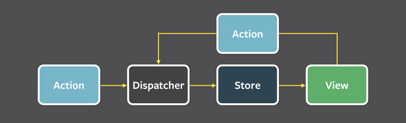
In the Flux architecture, the application state is hold in a data type called Store. A Dispatcher sends Actions to the store, which then updates the store state in response to these actions. When the store state has changed, the Views are notified to use the current state of the store to update their visual elements. The actions are either generated by external events or by the user who interacts with the views.
The View metaphor was invented to describe visual elements on a computer screen, but no one is stopping us from extending this concept to physical elements like buttons, LEDs or even motors. So from now on we assume that they are part of our view.
The Flux architecture promotes a unidirectional flow of information: Views are updated on a change in the store state but they never update the store themselves, only indirectly through the actions they send. This also separates the business logic that modifies the system state from the side effects that update the physical interfaces.
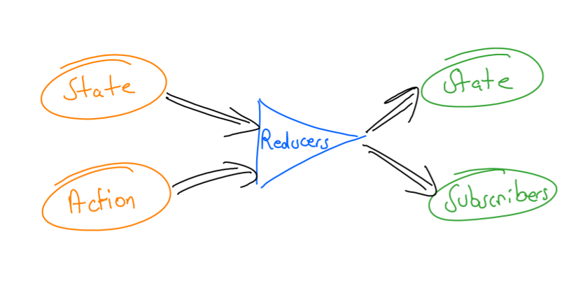
I am using a special version of the Flux-Pattern which was introduced by the Redux JavaScript library. It uses so called Reducers to modify the store state and Subscribers to update the views. Reducers are functions of the form (state, action) -> state and Subscribers are functions of the form (new_state, old_state) -> none (+ side effects). If you have some functional programming background, when looking at a reducer function, think of state as being an accumulator and action as an infinite collection or stream of actions that are reduced to a new state. Subscribers simply iterate over the infinite stream of (updated) store states.
We saw that when a button is pressed, the Buttons process creates a {:button, num} action that is passed to a action_dispatch() function. This function in turn passes the action to a dispatch() function of the Store module. The dispatcher then searches for reduce functions that transform the current store state with the given action into a new store state.
When the reducers are applied, all subscribers functions are called with the new store state. Some subscriber for example might watch for a change in the brightness value and set the LED brightness to match the new value.
Let's look at a typical scenario in detail and let us assume the user is on a page where he can set the maximum brightness of the alarm light.
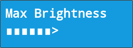
By pressing button 3 he can increment the brightness. This button press creates a button message that is sent to the dispatcher:
store = Store.new %{page: :max_brightness, :max_brightness: 5}
Store.dispatch store, {:button, 3}
The following reducer function executes when the store state contains an attribute :page with the current value :max_brightness and an action {:button, 3} is dispatched:
def reduce state = %{page: :max_brightness}, {:button, 3} do
  %{state | max_brightness: state.max_brightness |> Kernel.+(1) |> Kernel.min(15)}
end
The brightness is incremented and limited by 15. After the dispatch our store state looks like this:
%{page: :max_brightness, max_brightness: 6} = Store.state(store)Note here: since all data is immutable in Elixir, the reducer function creates a new state object with an updated max_brightness value. Also note that this function has no side effects. It is a pure function which can easily be tested.
The side effects are performed by the subscribers. Here is a subscriber function that updates the LCD to display the current max brightness value to the user:
def update %{page: :max_brightness, max_brightness: brightness}, _ do
  Lcd.draw_bar brightness
end
This update happens only when we are on the :max_brightness page.
Lets look at another subscriber, that updates the LED light to show the user how bright the LED light will be:
def update %{page: :max_brightness, max_brightness: brightness}, _ do
  Leds.light brightness
end
All the other parts of the system are implemented in the same way.
The firmware also contains a (rudimentary) web application written with the Phoenix framework. All of the clock parameters can be edited on a single web page. When the page is submitted, the settings are stored to the SD card and a :reload_settings action is generated an dispatched.
def create conn, params do
  settings = params["settings"]
  Settings.put :max_brightness, String.to_integer(settings["max_brightness"])
  Logic.dispatch :reload_settings
  render conn, "index.html", settings: get_settings()
end
The reducer for this action reloads the state from disk:
def reduce state, :reload_settings do
  %{state | max_brightness: Settings.get(:max_brightness)
end
And now, when the settings are saved through the web app and the user is also on the LCD page for setting the maximum brightness, automagically the display and the light are immediately updated.
Summary
The whole system is build from only a few architectural elements:
- A store the contains all parameters of the current system state
- Input processes that generate actions when hardware events (button presses, timer events) occur
- An action dispatcher that looks for Reducers that can handle a specific action in a specific state
- Reducer functions that transform the system state from the current state into a new one
- Subscribers that update the physical elements to match the new state by sending messages to output processes
- Output processes that control actuators like displays, lights or motors
That's it. That's the whole story. And it is kind of an old one: IPO, the input-process-output model. This model was invented when the first computers where available. Back then it described the process of feeding punch cards into big mainframe computers that spit out new punch cards after processing the input data.
But now we have this slightly modified IPO: State + Actions -> Reducers -> State + Subscribers
Try it out yourself
Since everything is modeled as a separate process, we can replace the input and output modules with simulators. So even if you don't have the alarm clock hardware, you can run the software on your local machine.
On the next page i show you how this is done.