Interrupts
At this point it becomes clear that we need to perform some things in parallel: read in characters received from the ACIA, periodically scan the keyboard, perform a soft reset and perform delays for blinking LEDs or playing scores with a SID (in the next part).
We could periodically check if some event has happened in our main program. This is called polling and for some problems in simple embedded applications this is a perfect solution. For example we could implement a state machine that is continuously executed in a loop, checks for events, executes actions if an event has occurred and changes its state accordingly. But what about a delay? The main program could execute a delay loop, but during this loop it wouldn't be able to perform other tasks. Especially it wouldn't be able to handle urgent events like fetching a received byte from the ACIA in order to clear the receiver buffer immediately.
We need a mechanism that interrupts the main program and executes a special subroutine in case of external events. This is called interrupt handling.
Circuit
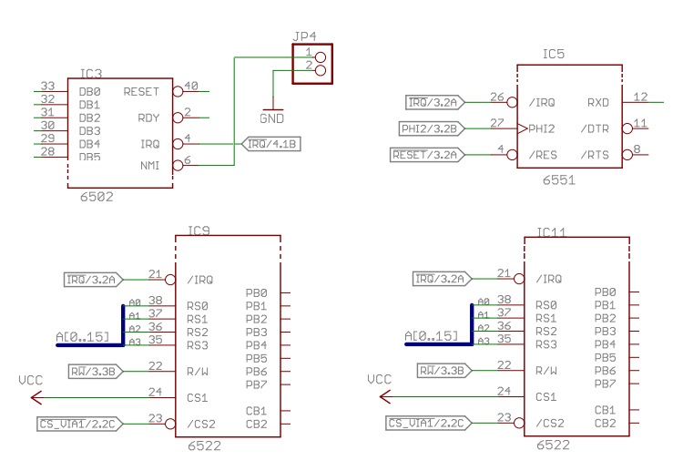
Most 6502 system chips have a special !IRQ output signal that signals if special conditions occurred inside the chip (for example a timer overflow or a byte received from a serial interface). These are low-active, open-collector signals so all !IRQ lines can be connected together and wired to the !IRQ input of the 6502 CPU. Interrupts on this input can be enabled or disabled, in contrast to the other interrupt input !NMI, which cannot be disabled.
I have connected the !IRQ outputs of the 6522 VIAs and the 6551 ACIA to the !IRQ input of the CPU. The !NMI will later be connected to a key of the keyboard, allowing a soft reset.
Program
This example shows how to use Timer 1 of VIA1 to perform the same blinking LED task as in the "VIA (Ports and Timers): Blinking LED" part. But instead of using a delay loop, we are using the Timer 1 interrupt. Essentially this code sets timer one to continuous mode, which means that the timer counter is loaded with the initial value TIMER_INTERVAL, decrements the counter to zero with every tick of ϕ2, signals an interrupt and reloads the counter with TIMER_INTERVAL again.
Now we have our irq_handler every 100 ms. We increment another memory counter in order to determine when one second has elapsed. In this case we toggle the LED and reset our custom counter to 0.
The other interrupt handler is nmi_handler This is triggered with a low signal on the !NMI and reduces the maximum number of the custom counter to 10. So when this interrupt is triggered, the LED toggles every tenth of a second.
As you can see, !IRQ interrupts are disabled with the SEI command enabled with the CLI command.
                  .setcpu "6502"

                  .include "io.inc65"

                  LED_DDR = VIA1_DDRA
                  LED_OUT = VIA1_ORA
                  LED     = VIA_PA7

                  TIMER_INTERVAL = 10000  ; One interrupt every 100 ms (@ 1 MHz)

                  .segment "VECTORS"

                  .word   nmi
                  .word   reset
                  .word   irq

                  .bss

ticks:            .byte 0
max_ticks:        .byte 0

                  .code

reset:            jmp main

nmi:              jmp nmi_handler

irq:              jmp irq_handler

main:             sei
                  cld
                  ldx
                  txs

init_led:         lda LED_DDR
                  ora #LED
                  sta LED_DDR
                  lda LED_OUT
                  and #>~LED
                  sta LED_OUT

init_timer:       lda #0
                  sta ticks
                  lda #100              ; Switch LED every 100 * 100 ms = 1 s
                  sta max_ticks
                  lda #%01000000        ; Continous running T1, disable PB7
                  sta VIA1_ACR
                  lda #%11000000        ; Enable T1 interrupt
                  sta VIA1_IER
                  lda #TIMER_INTERVAL
                  sta VIA1_T1C_H

                  cli

loop:             jmp loop

nmi_handler:      pha
                  lda #10               ; Switch LED every 10 * 100 ms = 0.1 s
                  sta max_ticks
                  pla
                  rti

irq_handler:      pha
                  lda ticks
                  clc
                  adc #1
                  sta ticks
                  cmp max_ticks
                  bne @irq_done
                  lda #0
                  sta ticks
                  lda LED_OUT
                  eor #LED
                  sta LED_OUT
@irq_done:        lda VIA1_T1C_L
                  pla
                  rti
PCB
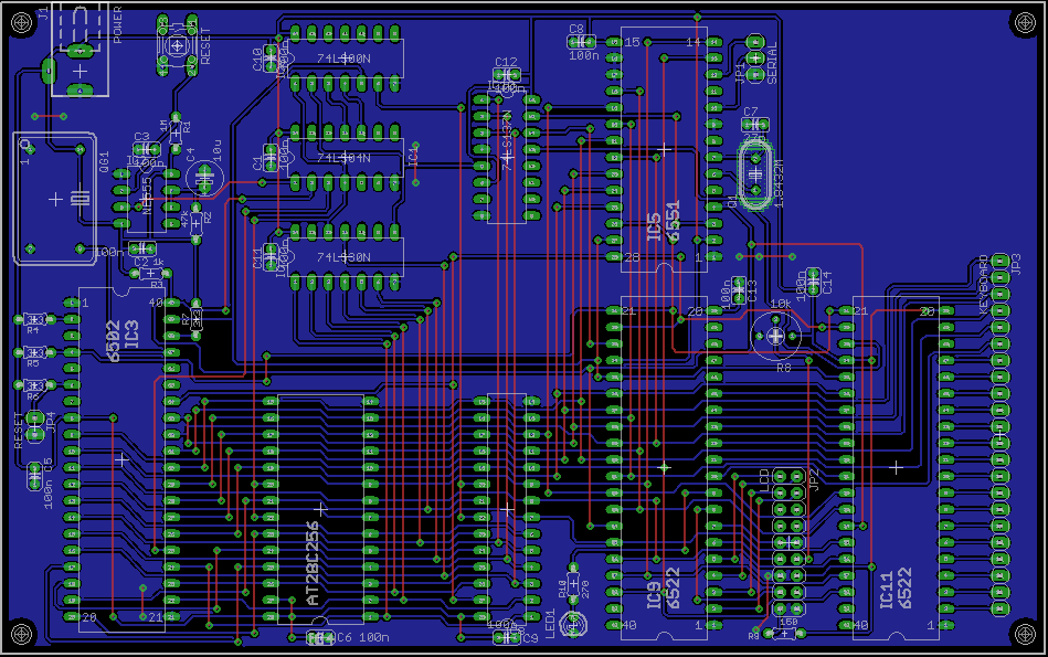
This PCB is mostly the same as the previous one. Only the !IRQ interrupt line has been routed to all peripheral chips.